


Summary
The following documentation describes a set of tools that automates the process of creating mosaics (aka montages for the better part of the last 3 years). Support for time-lapsed datasets as well as multiple mosaics has been added.
Starting up ImageJ
- All mosaic processing is expected to occur on Windows-based machines. The first step requires the mapping of a drive to access a networked copy of ImageJ. You may need to re-login to the machine for this to work.
- In Windows explorer, choose Tools->Map Network Drive...
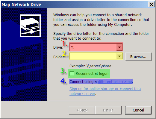
- Select any letter for Drive (1)
- Under Folder, type in \\ samba.crbs.ucsd.edu\tera5 (2)
- Uncheck Reconnect at logon (3)
- Click on Connect using a different user name (4)
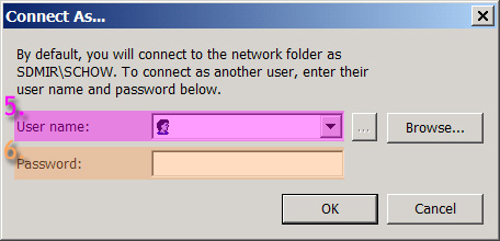
- Fill in your user name and password that you would use to access the tera drives (5) & (6)
- ImageJ can then be started by running "run_1Gbyte.bat" or "run_512Mbyte.bat" inside the x:\ImageJ-Mosaic directory where x is the letter you selected earlier while mapping the Drive. Difference of these starting files is amount of memory allocated for ImageJ - run_1Gbyte.bat allocate 1GByte memory and run_512Mbyte.bat allocation 512Mbyte. For creating mosaic, 512MByte of memory is enough.
Processing Images
- The first step of the mosaicking process involves taking the mosaic acquisition product taken from a microscope (either the RTS 2000, the Olympus Fluoview 1000, or some other microscope) and reading the images in their propietary formats. The images will then be converted over into some known organization of images into a microscope independent format. The plugin responsible for this task is -MEMontage->MEPreprocess.
- Run the plugin -MEMontage->MEPreprocess from Plugins.
- You will be prompted to select a file to open. Depending on which microscope the mosaic was acquired input images can be a single IMG file (RTS 2000) or a collection of TIFF files accompanied by a single log file (MATL_Mosaic.log for Olympus FV1000). For the first case, select the IMG file, and for the latter case select the log file to be opened.
- At this point a dialog will pop up allowing bleedthrough correction to be performed manually.
- You will be prompted to choose whether the file should be processed as a 3D dataset or a 2D maximum projection of the dataset. 3D datasets may be used for further volume reconstruction or stereo pairs. Click Yes for 3D dataset, and no for just the 2D projection. Note: A 2D Projection will be created for you even if you choose to process the images as a 3D dataset. Much more time will required for the steps involved in processing the mosaic if the 3D dataset selection was selected due to the increase amount of files saved. Please ensure that this option is selected only if the 3d dataset is absolutely necessary.
- Perform manual bleedthrough correction unless there is only 1 channel or two channels do not have any cross talk by sequential scanning and/or non-overlap emission bandwidths between dyes.
- Wait until the OK button is enabled on the status window. At this point, a folder containing the name of the file entered will appear. Within this folder, there are two additional 2 levels of directories, the first containing the different mosaics, the second containing the different channels for each mosaic. These directories are denoted by: MontageX and chanX where X in each case is some number. (Blue = chan1, Green = chan2, Red = chan3)
- At this point, all images outputted will be in pgm (raw) format.
- The order of the time lapsed images will be indicated by the number following the _t- in the filename.
- The order of z steps (if no Maximum Z Projection was selected) will be indicated by the number following the _z- in the filename.
- The order of t steps (if a time lapse acquisition was selected) will be indicated by the number following the _t- in the filename.
Image Normalization (optional)
To check whether image normalization is needed, run the plugin -MEMontage->ME_Combine and select a file from inside chan1 directory. If uneven illumination is present along the edges of each image, the resulting mosaic will not appear seamless. For more information.
Manual Image Alignment
- Run the -MEMontage->MEManual Align plugin.
- For detail instruction (or "h" to bring up a help window) for a manual for -MEMontage->MEManual Align.
- Open up the file that you want to align. These files are stored inside the chanX directories.
- Select a X slice where there are enough distinguishing features in the image to align manually. Align the pair of images, and right click on the image, select Apply displacements to all.
- Select a Y slice where there are enough distinguishing features in the image to align manually. Repeat.
- Right click on the image, select Save displacements. Then close the manual alignment window.
Peform the above steps for one channel only per mosaic. You want the images from each of the different channels to be in complete registration with each other.
Auto alignment and mosaic stitching
Depending on the size of the files, two possible types of files maybe generated. For images less than 4 GB, tiled tiffs will be created. Most image processing applications including ImageJ cannot open Tiled TIFF images natively (One notable exception is Adobe Photoshop). For images greater than 4GB, PGM files will be created. While most applications are capable of reading in a PGM file, the PGM file does not have the memory efficiencies of tiled tiff built into the format, and the entire raster will need to be loaded for display. TIFF is not used for files greater than 4 GB since it has file size limitation cap of 4 GB.
- The next task in the mosaic processing pipeline involves the automatic alignment of every single pair of images in the mosaic to minimize the discontinuity between adjacent images when the mosaic is assembled. Once automatic alignment is performed, positions of each of the image with respect to the final mosaic will need to be calculated and the images stitched together into one single mosaic. The alignments calculated will be used to determine the final image positions. The plugin that performs this task is -MEMontage->MECombine .
- Run the -MEMontage->MECombine plugin. Select the "Montage" folder inside the constucted directory in the "Open File" dialog. The following dialog will be presented:
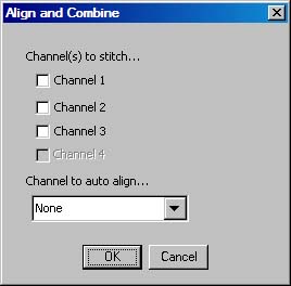
- Select all the channels that you wanted to have processed, and select the brightest (but not saturated) channel with the most coverage over the entire specimen area for auto alignment to be performed on. Coverage has a higher precedence over brightest channel when making this decision. These alignments will be applied to all other channels. If no alignments are desired or alignments have been performed once already, do not select a channel to be used for auto alignment. Currently auto alignment is performed only one channel and due to the nature of the dyes, there may not be complete coverage over the entire specimen for one dye. This means that auto alignment will be performed on areas where they may not be features to aligned with even though features are present in other channels stained with a different dye. Unfortunately, auto alignment is not capable of integrating alignments from different channels together and this makes selecting a channel with the most coverage important.
- The generated files will have the same filename as the original, except it will be appended by the keyword "Combined". The files created will be of the Tiled-Tiff format as long as the files generated are not over 4 GB. If they are, pgm versions of the files will be created.
- Run the -MEMontage->MERGB File Merge plugin to combine the different channel files into a single RGB file. Select the appropriate "Montage" directory once again in the "Open File" dialog. The following dialog will be presented:
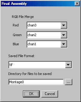
- A few options for the output format is given. If the files created from MECombine_ are TIFF files then the resulting file/files can be saved either as TIFF (if the resulting file is greater than 4 GB, compression will be enabled), PPM, or JPEG 2000. Otherwise, if only PGM files were created then the user is limited to just PPM or JPEG 2000. The compressed TIFF option is enabled primarily so that images may b e uploaded to Neuroinformatica.
-
The file format that is used for the final mosaic product will depend on how big the final mosaic data is and what are the anticipated processes to be done on the data. Below is a list of advantages and disadvantages for each of the file formats:
- TIFF : Adv: Commonly supported file format. Images are stored as tiles so that applications may not need to load the entire dataset into memory before processing. Disadv: No multi-resolution support (slow mosaic zooming for large datasets). 4 GB File format limit.
- TIFF with compression: Adv: same as TIFF. Disadv: Slow to load (tiles will need to be decompressed first). 4 GB File format limit still exists (but because the image data is now compressed, more image data can now be stored than with the uncompressed format. This format was enabled largely to be compatible with Neuroinformatica and Zoomify.
- PPM Adv: Very simple file format, most imaging applications will have no problem opening this as long as the dataset can fit into memory. No file size limit. Used primarily as a way for other programs to perform other file format conversions on. Disadv: Images are stored as a single tile raster. Only very specialized programs (ie custom programs) will be able to open these files. We currently have no viewers for large scale mosaics saved as PPMs.
- JPEG2000 Adv: Multi resolution format support. Very high file size limit 2^32 pixels in X x 2^32 pixels in Y. File is compressed in a lossless way, saving disk space. Disadv: Not much program support for this file format.
- If the dataset is relatively small and was saved as a TIFF, run the -NCMIR->ME Tiled Display to display images created with either MECombine or MERGB File Merge
- Manual for METiled Display.
- If the dataset is large and saved in another type of format, read the following section to see methods on how to view the mosaics.
Further notes regarding really large mosaics
While the routines described above are scalable to very large datasizes, interacting with the data created can be excruciating. METiled Display will not be able to handle such datasets in a responsive way and an alternative is needed to view the data. A better alternative is to use the Er Viewer (Earth Resource Mapping) viewer to open the tiled-tiff datasets since it handles the data better than METiled Display. Unfortunately there is still a considerable amount of lag in viewing the data and much waiting is required. Currently, the best alternative to using TIFF altogether is to save a copy of the data a JPEG 2000 file. JPEG2000 uses multi-resolution encoding of the source file allowing the user to view the data at multiple scales in a fluid manner. The drawbacks of using JPEG2000 are that most image processing applications are not capable of opening the datasets and that it takes a tremendous amount of time (~30 min for a 4 G file) to encode. To encode the dataset as JPEG 2000, select the output format in MERGB File Merge to be "jp2". JPEG 2000 files can be opened with either the ER viewer or the kdu_show (found in the Kakadu folder inside the ImageJ directory). The ER viewer offers the user more intuitive method to navigate the data while kdu_show is more responsive. The kakadu (which includes the encoder and viewer) can be found at here and the ER viewer can be found here under Downloads/Plugins.